")
")
ThinSimulator
ThinSimulator module is a product designed by NC s.r.l. to simulate the tool path starting from any ISO file of CNC milling and turning .
ThinSimulator allows programme verification without engaging the machine tool and significantly reducing the time to set up a part programme.
It can be used both for a final verification of the ISO programme by checking sub-programmes and machine functions that cannot be displayed in a CAM, and in the modification of existing programmes by assisting the operator with a syntactic check and a graphical display of the changes made.
Customizable
The software uses of the same configurations of NCEVAL module for the recognition of the syntax of the various CNCs . It allows three-dimensional visualization of tool path, fixtures, stock and tools. The application configuration allows the definition of tools and machine origins and the management of the machine toolstore.
ThinSimulator adapts to the information provided by providing different degrees of help depending on the data available.
- The minimum requirements are the ISO programme and simulation configuration consisting of ISO interpreter and syntax definition.
- Allows editing with a syntax check, calculation of machining times and a basic simulation of the ISO program with automatic tools
- Add tool magazine
- Allows correct display of tools in use
- Add your own programming rules
- Allows for additional programming control
- Add finished part graphics
- Allows machining to be matched to the workpiece model
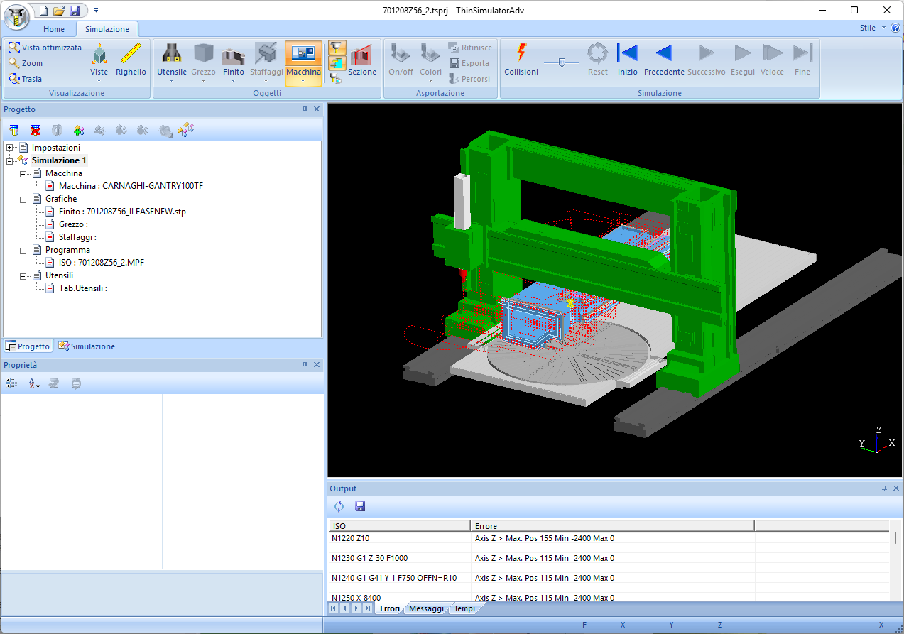
- Add machine graphics
- Allows an overall dimensions and collision check and tooling management
- Add blank graphics
- Allows material removal with collision check and comparison between finished model and machined blank
Precise
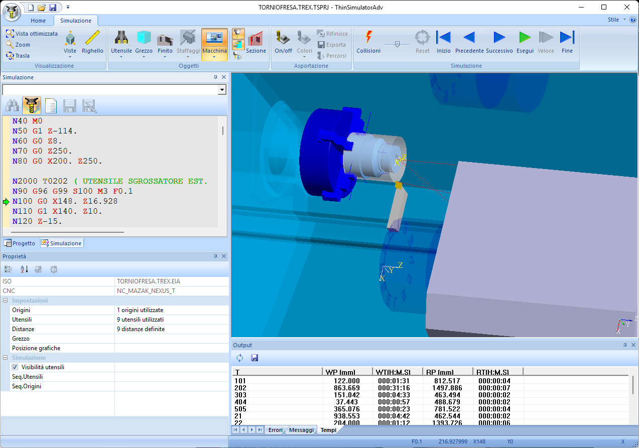
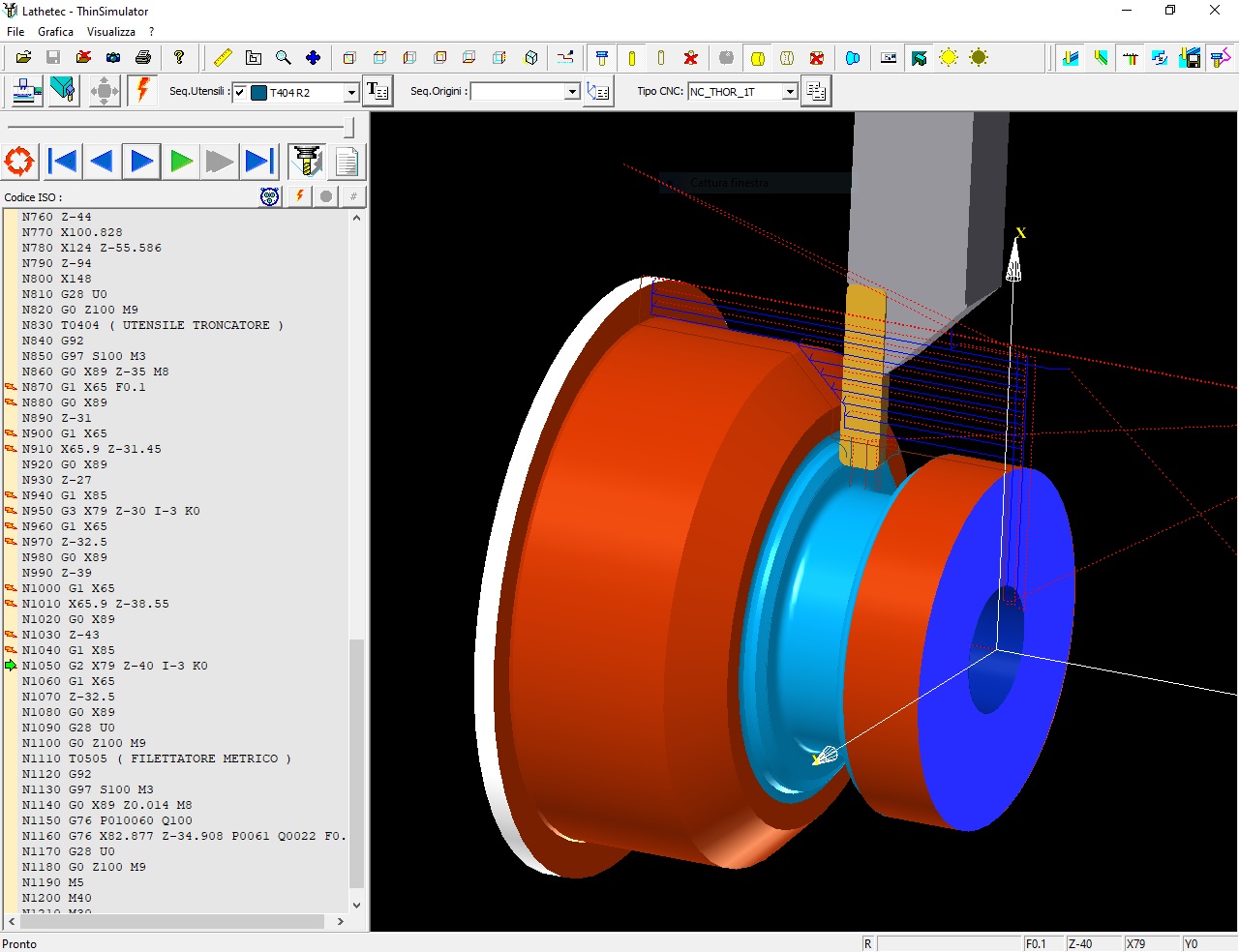
With ThinSimulator you can visualize toolpaths on different work planes (rotary table), 3D machining and turning. The product allows the visualization in solid, transparent form, 3/4 of the raw/finished piece and tools. It is possible to simulate the processing block by block and query the block that generated a movement on the screen. In addition, it is possible to manage the removal and finishing of the raw material.
In order to concentrate on checking parts of the path, it is possible to deactivate the display of rapids and some unnecessary tools and to match each tool with a particular colour. The tool forms for both lathe and milling cutter are the same as those used in the TOOL2000 processor and can be defined either by the processor or by a CAD via the DXFInspector module or via a 3D file.
The definition of a simulation project allows the settings defined in the simulation to be archived for subsequent quick review and effective archiving.
Accurate
- Immediate simulation of ISO path only for programme identification
- Management of tool sequence, related 2D/3D graphics and tool magazine
- Origin sequence management
- Management of automatic change of heads and/or tools
- Quick modification of ISO code and its verification
- Verification of ISO code and customisable programming rules
- Simulation of workpiece, fixtures, tooling and machine graphics
- Integration with Tool2000/TRex for rapid tool and path simulation
- Stock removal and finishing management
- Machining time estimation
- Collision check with all machine parts
- Analysis of results with comparison with reference model
- Measurement of the object produced
- Filing of a report of times and notifications highlighted during the simulation.